Auxiliary battery not charging while driving: causes and checks
 Spaziou
Real problem · Power
If you drive for miles but the leisure battery barely charges, separate alternator faults, activation signals, DC-DC charger, wiring and battery. Do not buy a bigger charger until you know where the energy flow stops.

Quick diagnosis
Check where charging stops progressing.
The DC-DC charger does not switch on at all
Check fuses, earth, positive input and D+/ignition signal if used. With smart alternators, the charger must also suit their operating behaviour.
It switches on but delivers few amps
Measure input and output voltage with the engine running. Thin or long cables and poor connections can limit current even while the charger is operating.
Charges, then cuts out
Temperature, current limit, battery profile or low-voltage protection can reduce or stop DC-DC charging. Check status indicators or diagnostic codes first.
Step-by-step test
Do not change the charger without measuring.
1 · Battery before starting
Note voltage or state of charge before starting the engine. Repeat with the engine running and major loads off. This shows whether energy is actually entering the battery.
2 · DC-DC input
Measure at the charger's input terminals, not just the starter battery. Low incoming voltage points upstream: fuse, wiring, earth or alternator strategy.
3 · Output to the battery
If input is correct but output does not match the expected profile, check charger settings and battery-chemistry compatibility.
Euro 6 and smart alternators
Why it may charge for five minutes and then stop.
1 · Voltage rises when starting
The voltage-sensitive relay sees the increase and connects starter and auxiliary batteries, making everything appear to work.
2 · Energy management reduces alternator output
A smart alternator need not stay near 14 V. Voltage may drop while driving to reduce consumption or follow regenerative strategies.
3 · The VSR opens
Below its voltage threshold, the relay assumes the engine is no longer charging and separates the batteries. The engine keeps running but energy stops reaching the auxiliary battery.
Relay or DC-DC
The right question is how your charging system behaves.
Relay / VSR
It may remain viable with a conventional alternator and compatible design. Its weakness appears when it relies on a voltage threshold modern vehicles no longer maintain.
DC-DC
Controls charging current and profile between starter and auxiliary batteries. Commonly used with variable voltage, start-stop or LiFePO₄, always sized for the vehicle.
Engine-running signal
This may be automatic detection through voltage/control logic or an external IGN/D+/CAN signal, depending on the manufacturer. Do not confuse this control signal with the cable carrying charging current.
Guided test
Where does charging disappear?
Three models to compare
DC-DC chargers already documented on Spaziou.
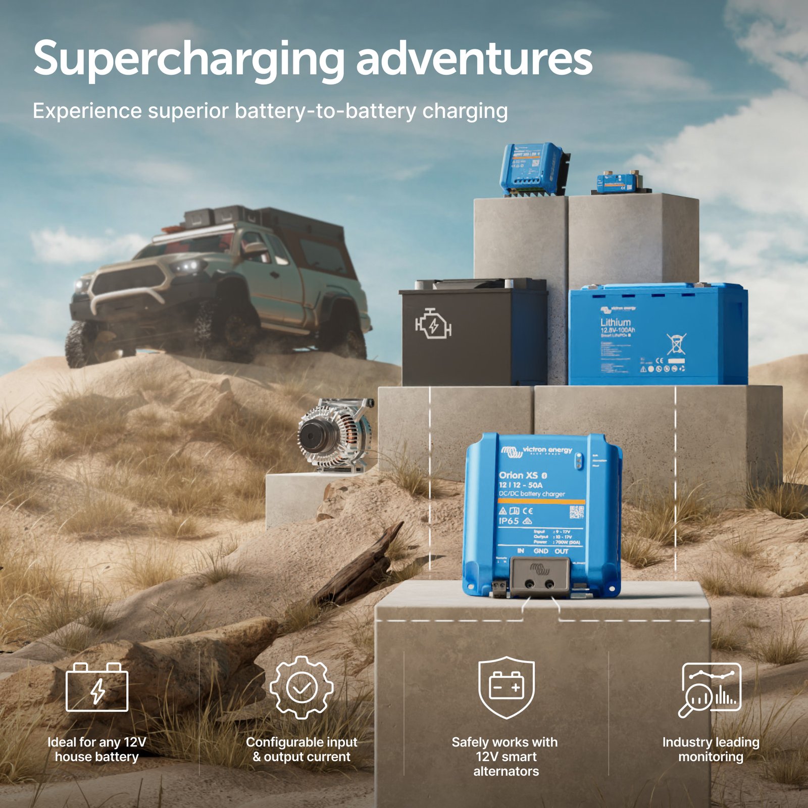
Victron Orion XS 12/12‑50A
A 50 A option for systems needing fast charging and Victron ecosystem monitoring/configuration.
View DC-DC comparison →View Orion XS on Amazon →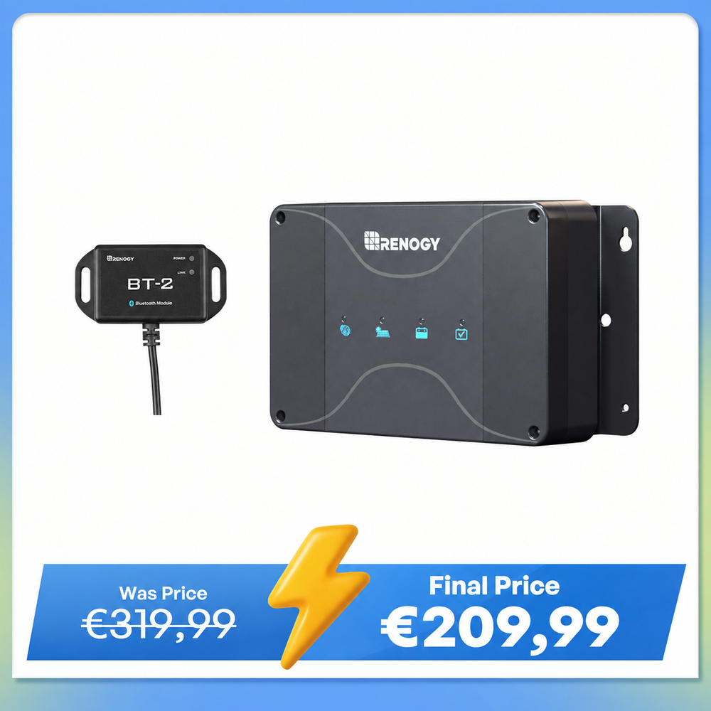
Renogy DCC50S 50A
Combines alternator charging and solar input. Useful for integrating both sources in one unit.
Compare specifications →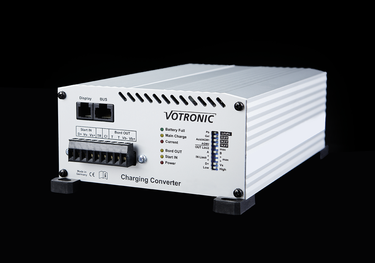
Votronic VCC 1212‑50
Another 50 A model. Check battery profile, wiring, ventilation and alternator control before choosing.
View comparison →Frequently asked questions
Questions about a battery that will not charge while driving.
Do I need DC-DC charging with a smart alternator?
This is common in modern vehicles because alternator voltage varies and a simple relay may not ensure proper charging. Decide according to the vehicle and existing system.
Are more amps always better?
No. Battery, BMS, alternator, cables and cooling all have limits. Higher-current chargers may need different cables and fuses without providing a useful improvement.
Could the battery be at fault?
Yes. A BMS limiting charging for temperature, voltage or protection can make a DC-DC charger appear faulty. Check battery status if monitoring is available.
Buying decision
Buy after finding the bottleneck.
Wiring or activation fault
Fix the fuse, signal, earth connection or cable size first. A new DC-DC charger connected to the same fault may behave just like the old one.
The equipment is undersized or incompatible
If input and wiring are correct but the charger cannot support the battery chemistry or current required, compare replacements sized for the complete system.
Tools for checks before replacing parts
Measure charging and fix connections.
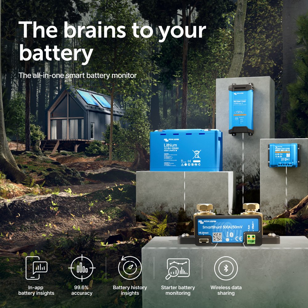
Victron SmartShunt 500A
Useful for seeing actual charging current while driving and checking whether the battery bank receives what you expected.
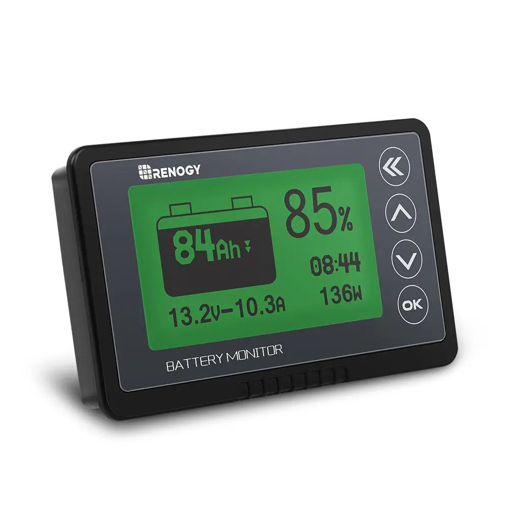
Renogy RBM500
An option with a local display to check current and energy balance without a phone.
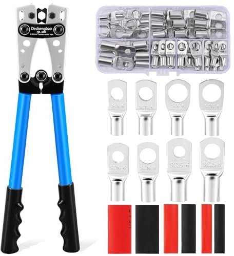
HX-50B · crimping tool
If a poor termination is at fault, redoing the crimp with the correct terminal and die may matter more than buying another booster.
Technical sources · reviewed 24/09/2026
Smart alternator, engine detection and IGN signal.
Victron Orion XS
Victron documents automatic engine detection, smart-alternator compatibility and optional external signalling when vehicle voltage does not reliably identify engine running.
Renogy DCC30S / DCC50S
Renogy states that smart-alternator installations must use the ignition port and included IGN signal cable.
Votronic VCC
Votronic publishes a 10.5–16.5 V input range for Euro 6 and D+/ignition/voltage activation diagrams depending on the version.